Palindrome
In 2028, new EU eco-regulations will require vacuum cleaners to be twice as energy-efficient. At SharkNinja, the strategy was to design a vacuum that could clean just as effectively on the backward stroke as on the forward stroke. That's how the Palindrome vacuum concept was created.
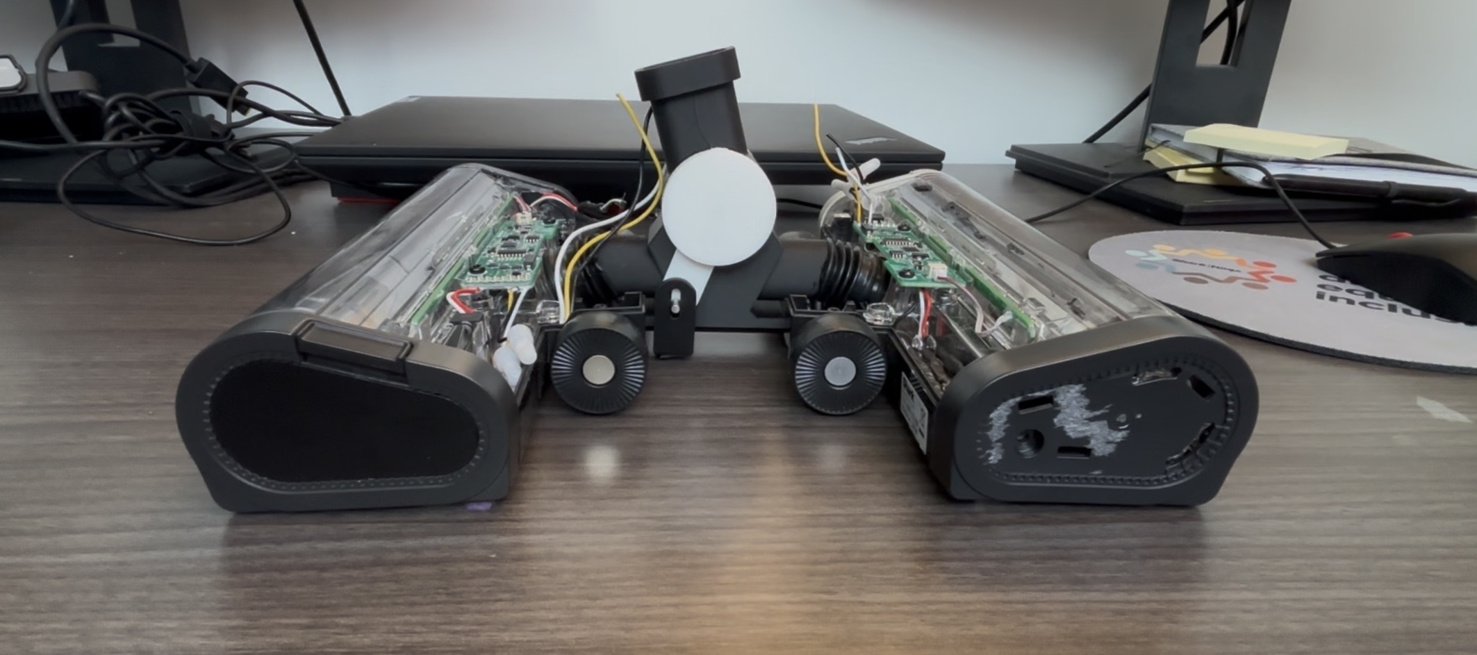
The main element determining reverse-stroke performance is the vacuum nozzle, and during my time at SharkNinja I worked on improving existing designs and developing new concepts for future products. My personal goal for Palindrome was to develop a working proof of concept and establish a design direction that the R&D team could build on and iterate after my co-op ended.
Goals & Limitations
Project Goals
- Get maximum debris cleaning. Current intake designs get ~70% pickup on the backward stroke vs. ~100% on the forward stroke — is it possible to get 100% in both directions?
- Create a maximum efficiency nozzle. Current tests take 3–5 strokes — can this nozzle design achieve parity scores in 2 strokes?
Limitations
Conventional nozzles have a brushroll before the suction inlet that agitates the material and lifts debris off the surface, which is then sucked up. Behind the suction inlet is a bristle strip that contacts the ground to create a seal and maximize suction.
Current designs have three problems:
- In the reverse stroke, the rear seal is opened, creating suction loss and less effective reverse cleaning
- The rear seal does not open enough, causing a buildup of debris ("snow piling")
- The rear seal opens too much, causing debris to hit the brushroll and shoot back toward the user ("spit-back")
| Debris Type (20g) | Debris Size | Debris | Forward Stroke | Backward Stroke |
|---|---|---|---|---|
| Sand | Fine | Dense | 98.75% | 47.9% |
| Coffee | Fine | Light | 99.15% | 99.05% |
| Rice | Large | Dense | 99.5% | 91.5% |
| Crushed Cheerios (7g) | Large | Light | 95.57% | 1.24% |
Current design struggles with fine + dense and large + light debris types due to snow-piling, especially on the backward stroke.
Reverse Intake Vent
My initial concept was based on an existing nozzle. I focused on eliminating spit-back and separating the air pathways for the forward and reverse strokes.
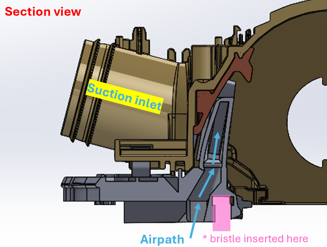
I designed a nozzle base that splits the airflow between forward and reverse directions. The reverse airpath bypasses the bristle strip to avoid compromising the seal and eliminating any spit-back.
Initial tests with split airpath:
- Split airpath causes significantly weaker suction in both forward and backward directions
- Lack of agitation in the backward stroke led to no pickup
Tests with 100% airflow to the back vents:
- Back intake still had limited success
- Could not eliminate snow buildup at the nozzle ends despite multiple design iterations
Learnings
- Working within existing designs is not viable for this concept
- Complicates the airpath too much
- Tight airpaths can maximize the venturi effect and suction, but airflow becomes the limiting factor for good cleaning
- Reverse pickup will never be 100% without a brush roll to agitate and lift debris off surfaces
Palindrome: Mirrored Nozzle
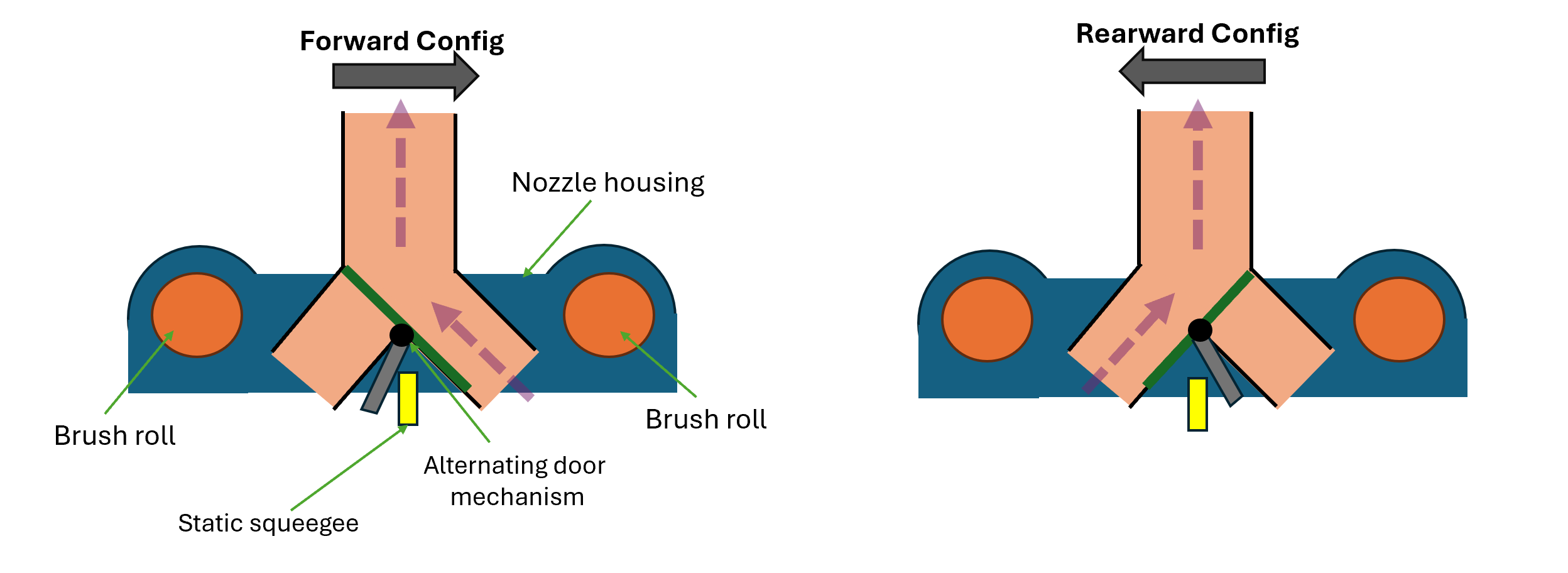
From the reverse intake vent, I realized that effective cleaning would require agitation in both directions. This led me to design a mirrored nozzle featuring a brushroll, intake, and bristle strip on each side. The main challenge was designing an alternating valve that could redirect the airpath based on the direction of the stroke.
Palindrome (w/o brushroll) vs. Current Nozzle (PowerDetect)
The prototype Palindrome performs identically in either direction, while the PowerDetect struggles and "snow-piles" on the reverse stroke.
Alternating Valve Development
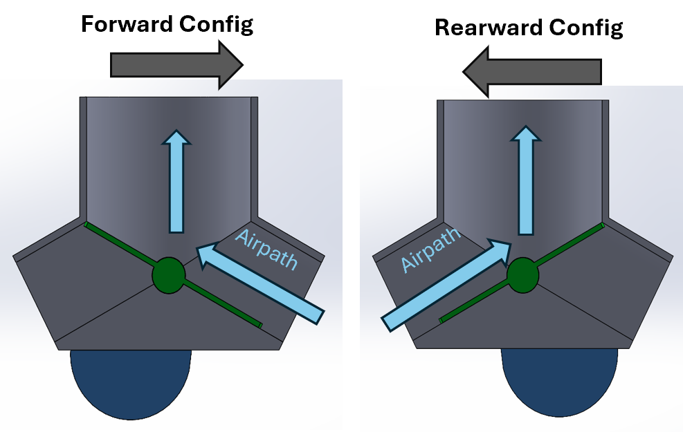
- Debris ingress big concern at pivot axis
- Redesigned slot geometry to minimize dust ingress
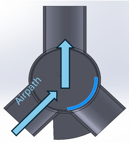
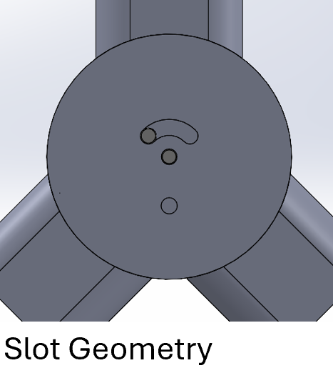
- Mechanism would not allow for rubber seal: no radial force that could create a seal
- Added additional CAM slot to create a lifting motion for the door
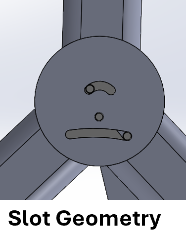
- Adds motion to the door (pops up then across)
- More force needed to articulate the system
- Changed to a straight CAM to reduce friction
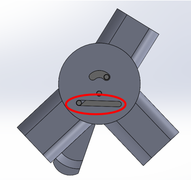
- Debris ingress is noticeable after some testing with sand
- Smoother/easier articulation
- Full articulation; open or closed
- Dual nozzle attachment using two nozzles back-to-back and connected to FW 3.0 (Light vacuum)
- Inconsistent articulation: not enough friction between ground and pivot (using hot glue as grip)
- Not enough suction to pick up debris without a brush roll
- Partial airflow leakage through closed valve
- Reduced number of components
- Internalized moving sections to reduce air leakage and improve prototype robustness
- Reduced overall size
- Adapted the nozzle to a PowerDetect for higher suction
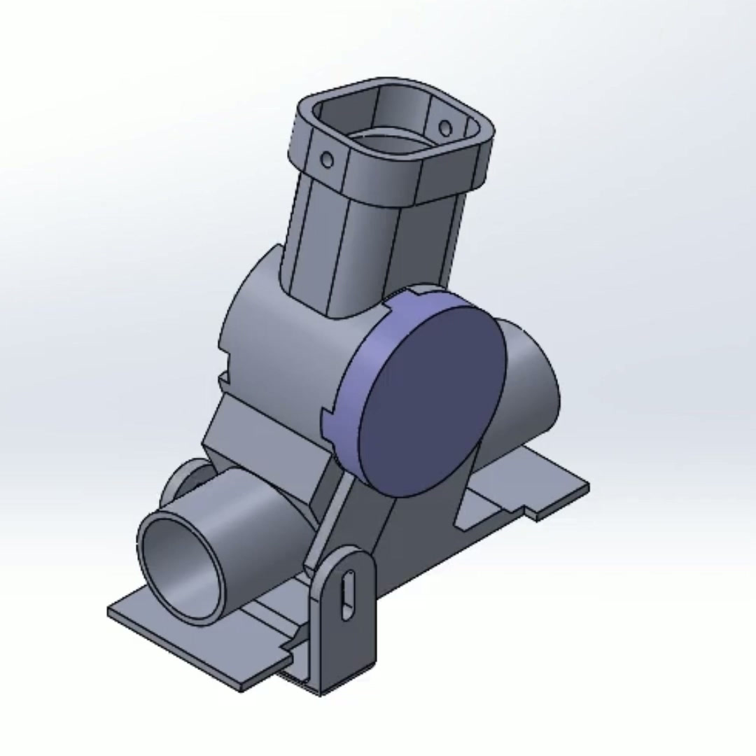
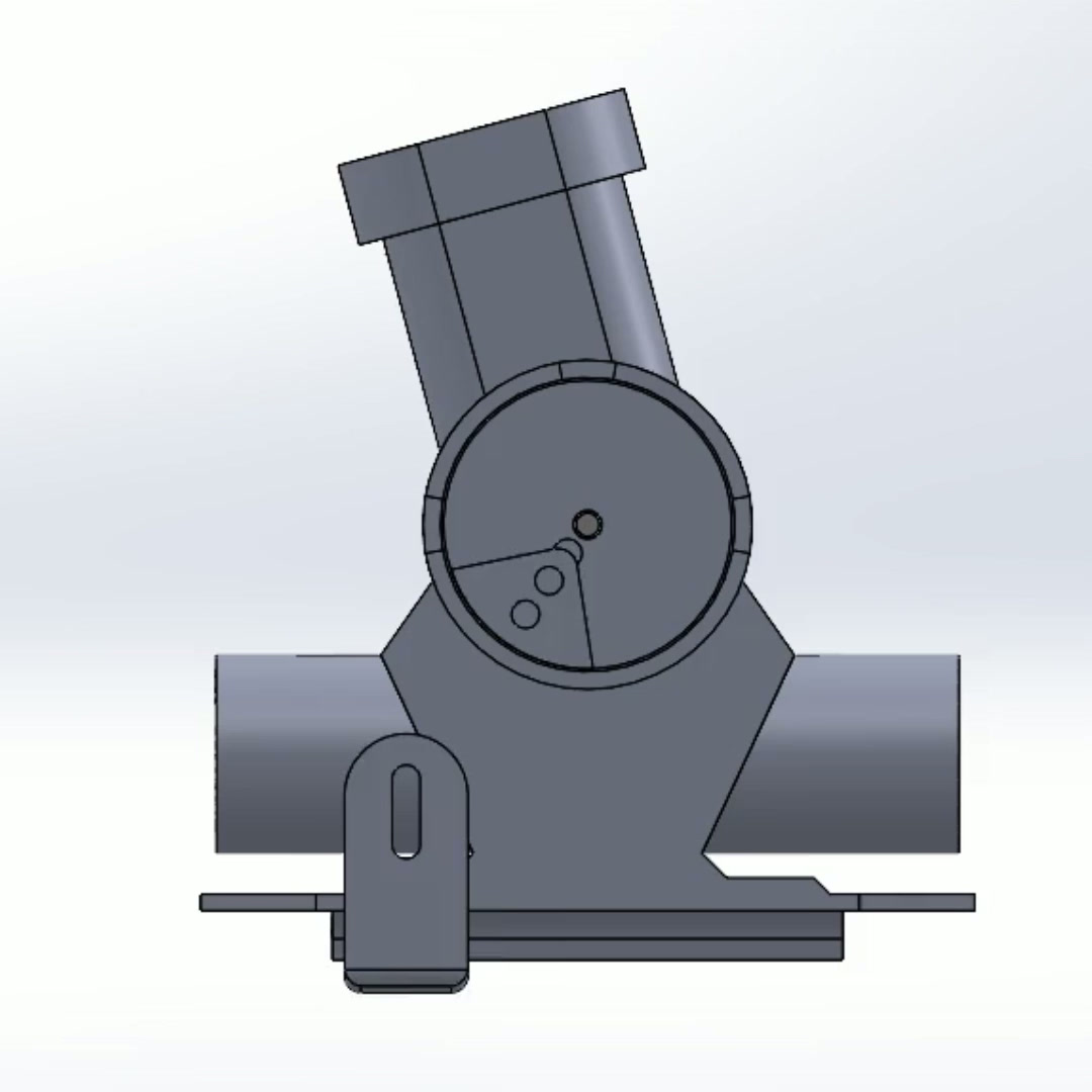
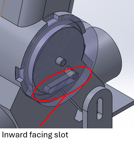
- Bottom-facing slot will accumulate debris
- Increased push-pull force from feet with no change in the y-axis
Next Steps for the R&D Team
- Determine current nozzle efficiency: run debris tests with 2 strokes (forward-backward)
- Determine static bristle strip performance vs. Eco-Edge/SharkGill: run tests with a static bristle strip on current nozzles