Personal Project
5-Axis Robotic Arm
A servo-powered robotic arm with a direct, smaller-scale replica controller — designed, printed, and wired from scratch.
Project Goals
- Design a robotic arm with five axes of rotation
- Create a control system using potentiometers and a direct, smaller-scale replica
- The controller has to be intuitive and user-friendly
- Robot must move smoothly and without delays between the controller and arm
- Create a simple grabber mechanism
- Can pick up and place objects up to 0.5 lbs
- Overall, it must have a clean aesthetic
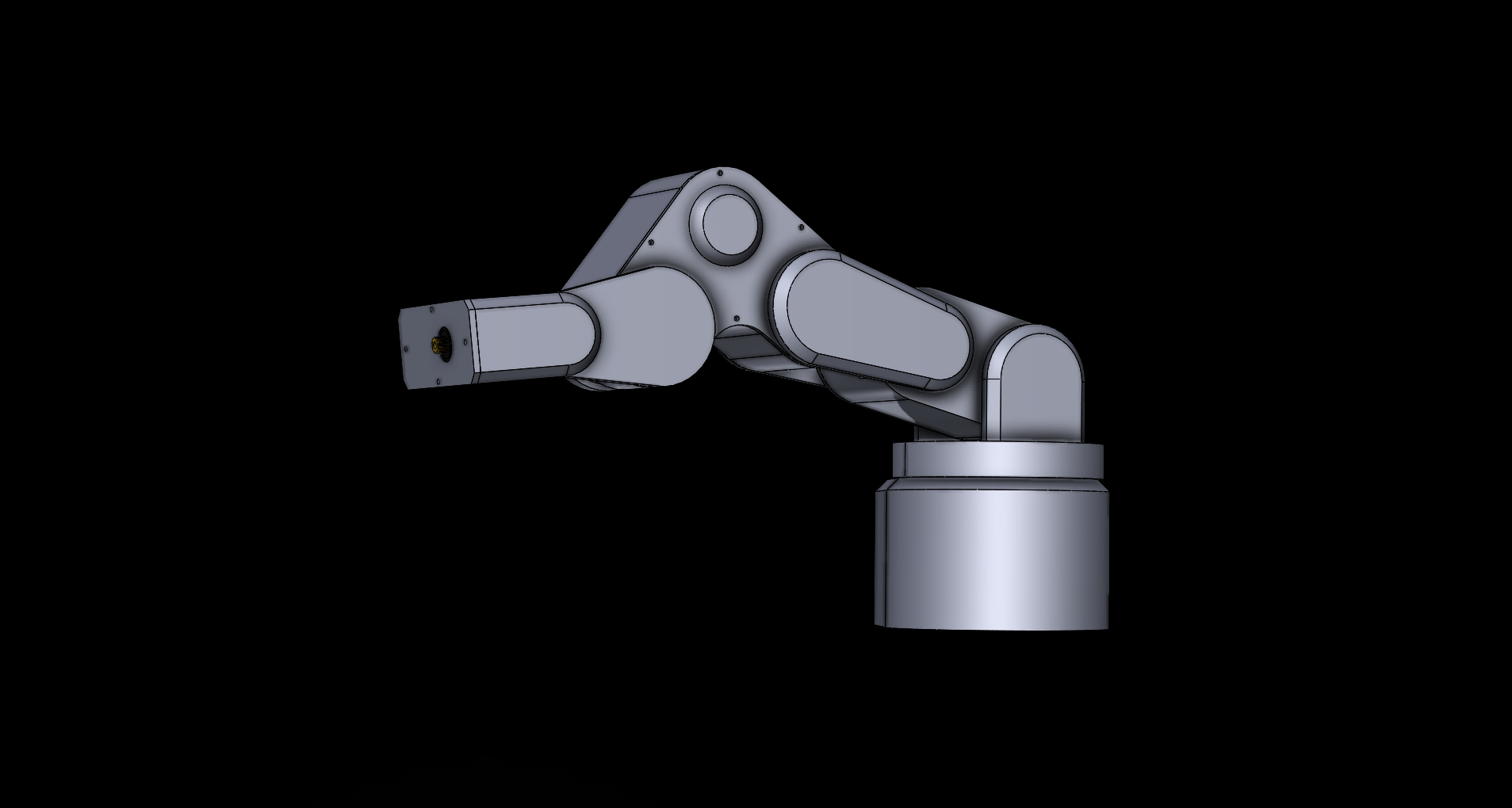
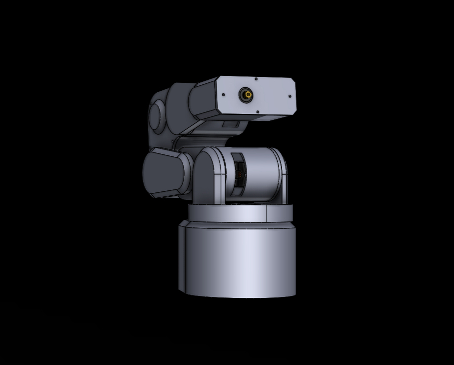
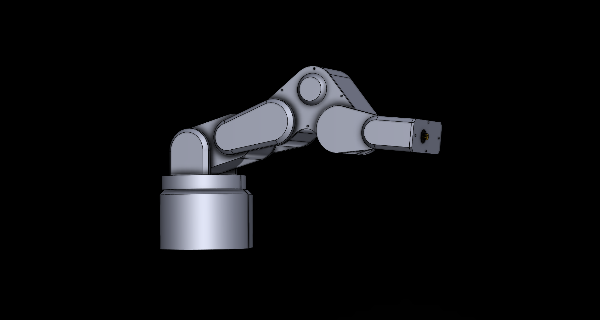
Initial Design on SolidWorks
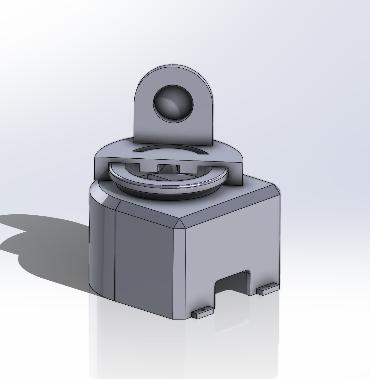
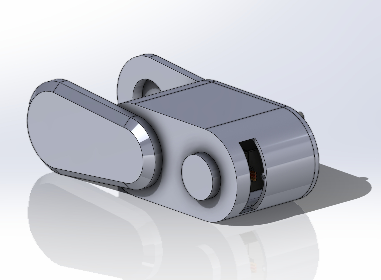
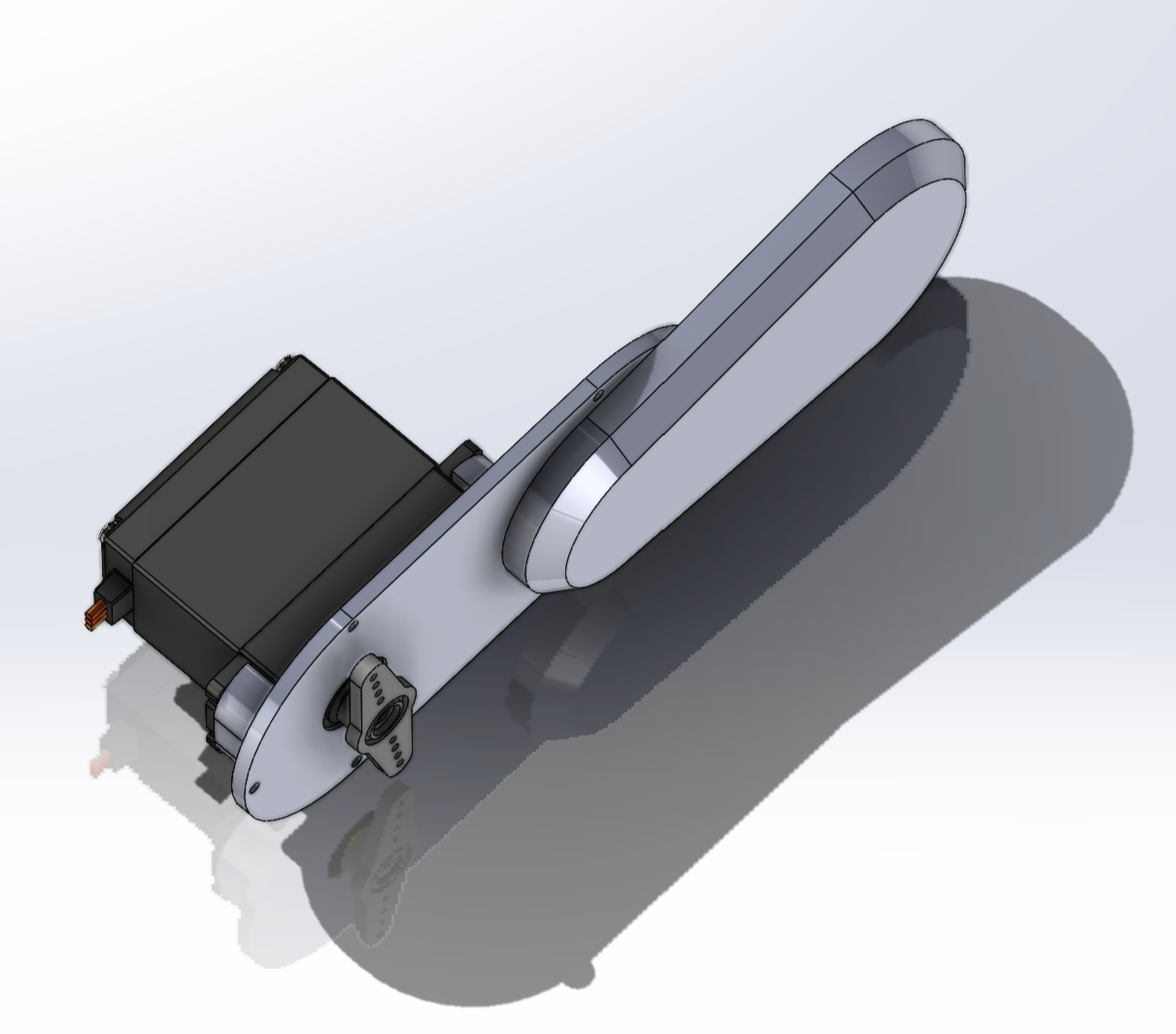
Created an initial CAD prototype based on the MG996R servo motors and prepared each section for initial print.
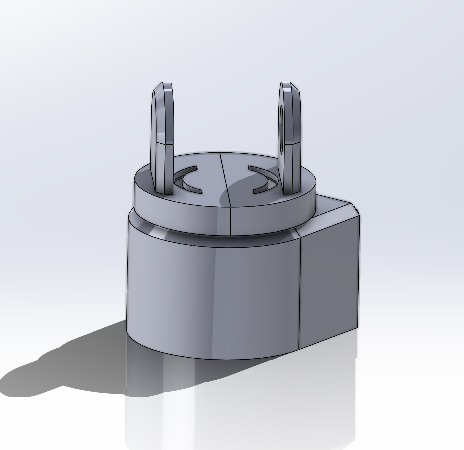
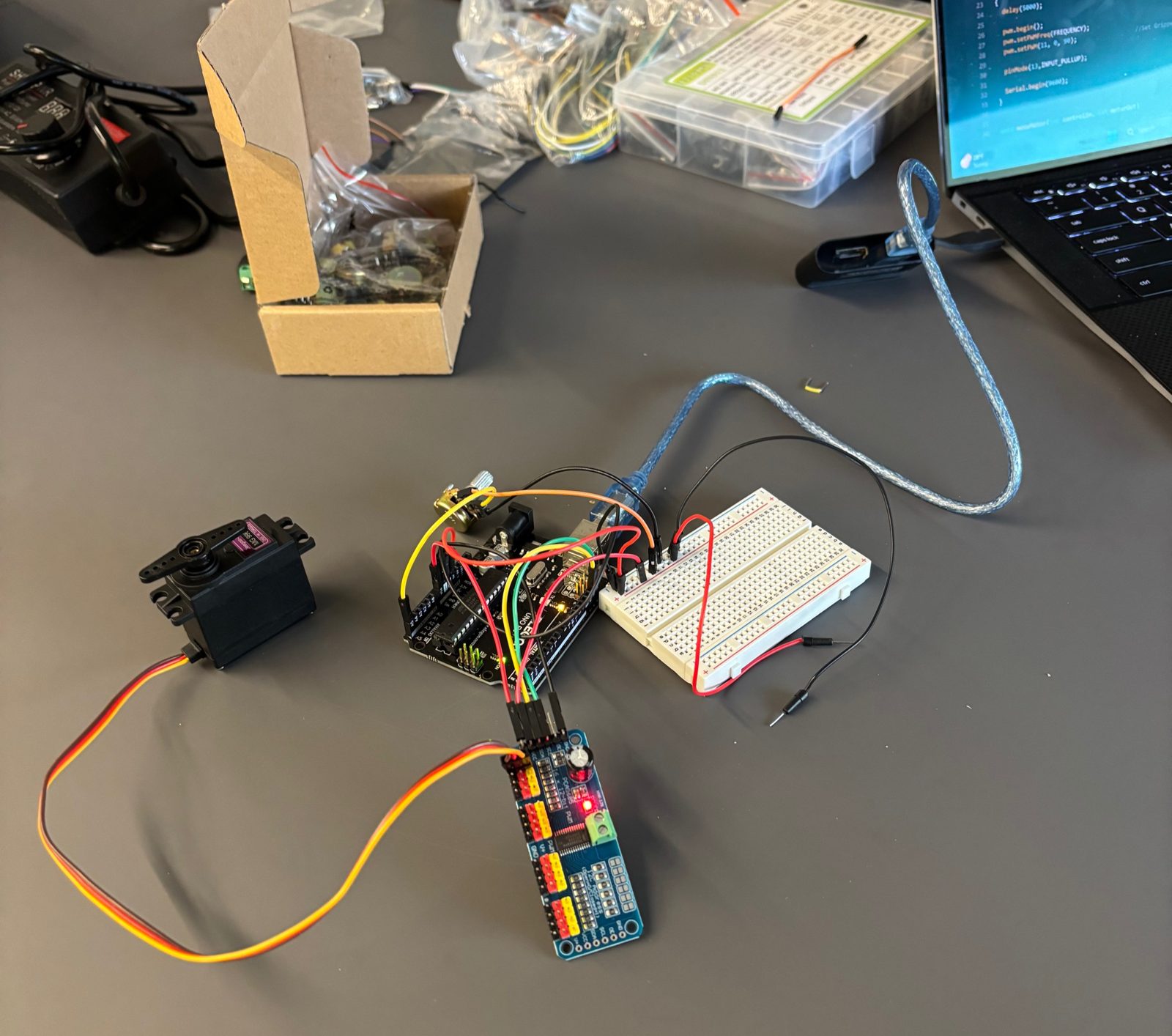
Wiring & Arduino
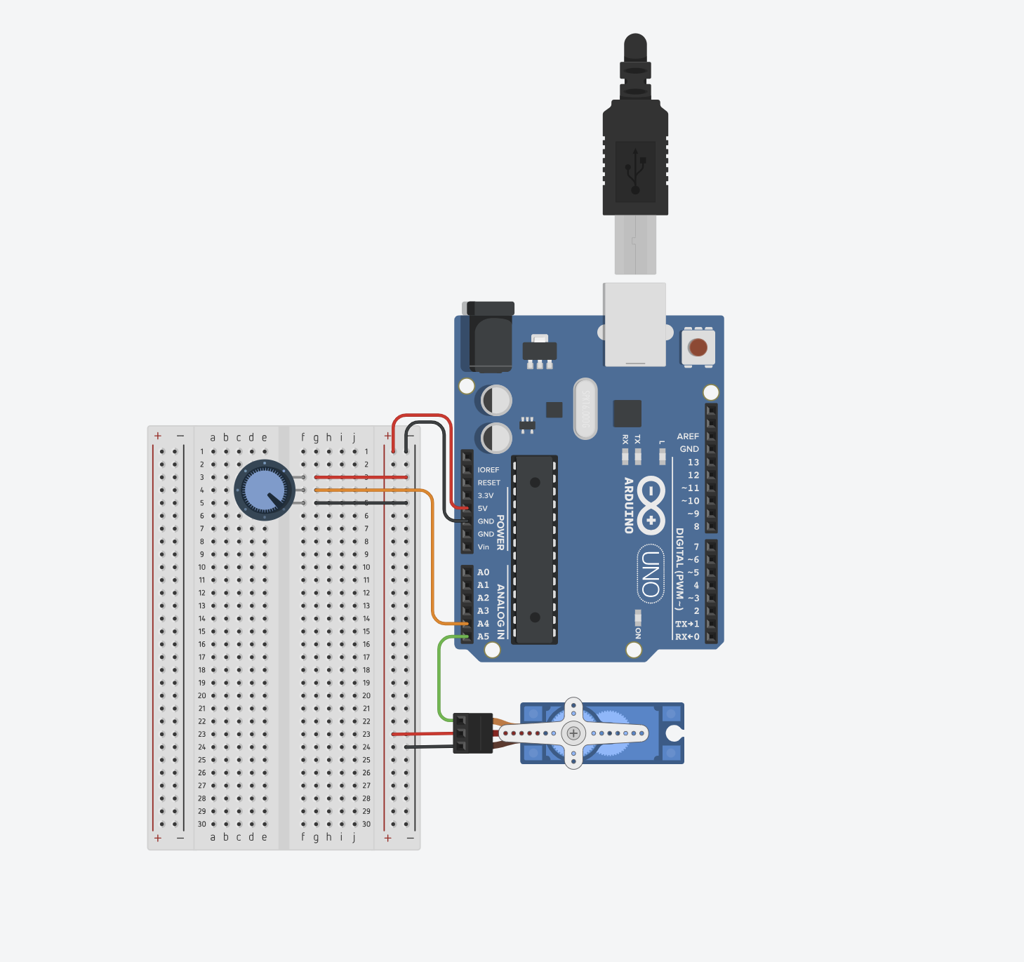
Currently working on the wiring and Arduino program. The goal is to link the potentiometer rotation with the servo rotation with minimal delay, while adding 4 more servos controlled by separate potentiometers.
First prototype notes
3D model and printing
- Increase the tolerances for each part — fast, low-quality prints caused joints to grind together
- Increase wall width to 3 mm for structural stability
- Add indents for screw heads so there is no interference during movement
- Better align wire slots for smoother assembly and movement
Arduino
- Individually adjust each servo range once the arm is assembled
- There is not enough current to power five servos
Revised Design
3D model and printing
- Simplified design to single-shear joints for easy assembly and increased tolerances
- Added countersinks
- Changed base design for better stability
Arduino
- Added 2200 μF capacitors to minimize voltage fluctuations when 5 servos are activated
- Cleaned up and streamlined the wiring to have a common ground for the system