Investigating Heat Transfer Enhancement in a Solar Trough
Global energy demand is rising, yet renewable technologies like concentrated solar power (CSP) remain limited by low operating temperatures. Our team built a rotating particle-flow receiver to test whether integrating solar particles into a parabolic trough system meaningfully increases working fluid temperature.
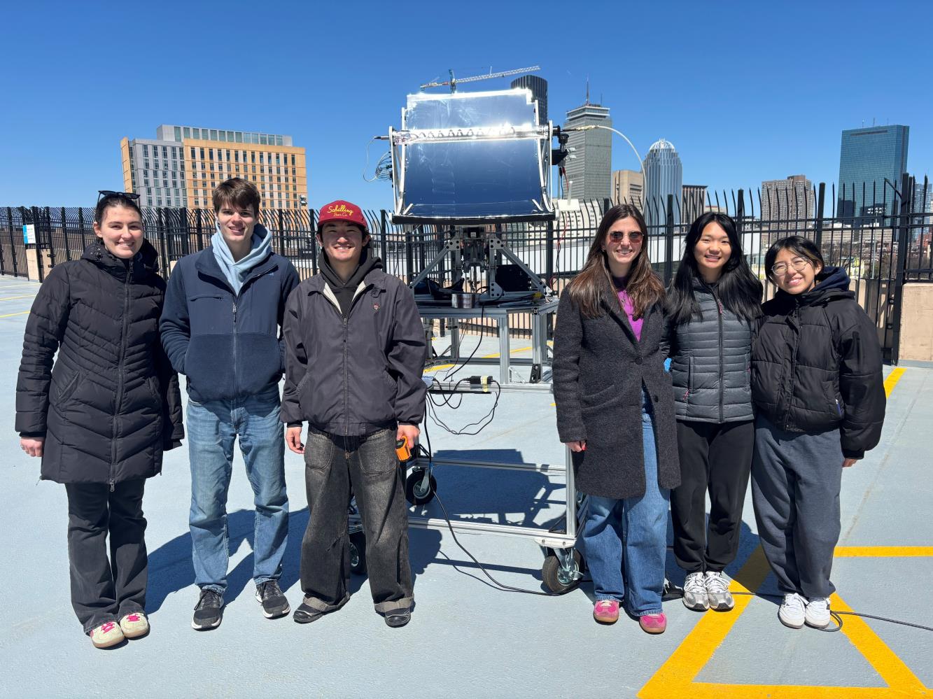
How It Works
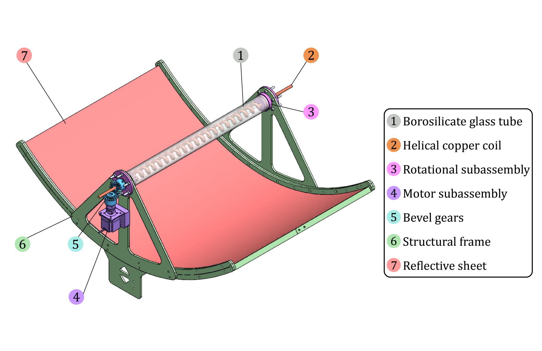
System CAD Design
- Borosilicate glass tube
- Helical copper coil
- Rotational subassembly
- Motor subassembly
- Bevel gears
- Structural frame
- Reflective sheet
Design & Testing Process
From first sketches to a full outdoor test rig on a Boston rooftop.
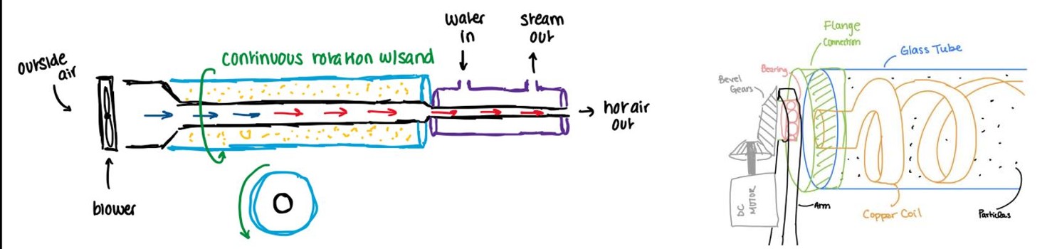
Sketch Development
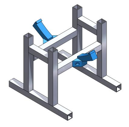
Fixture Trough
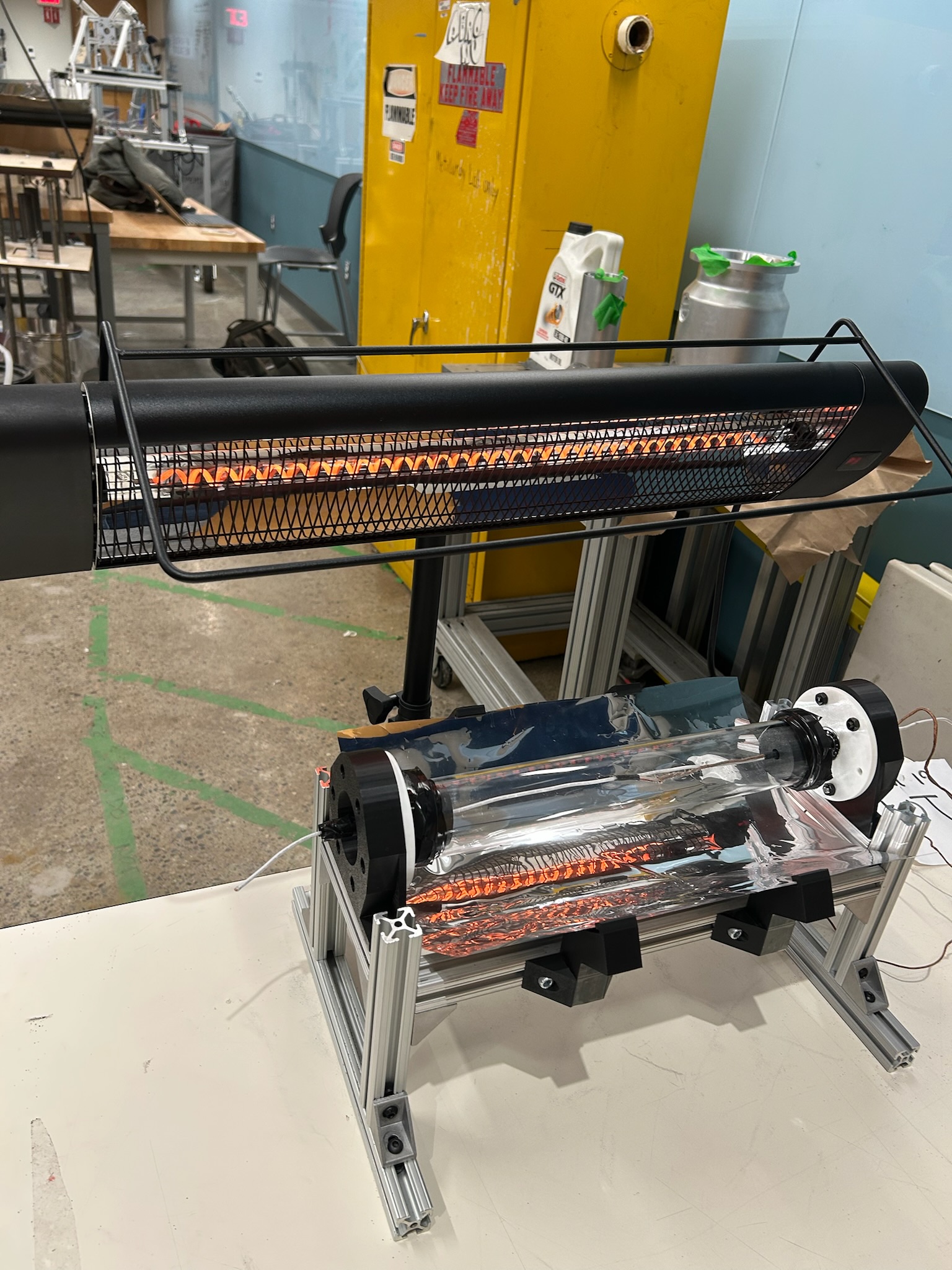
Fixture Testing
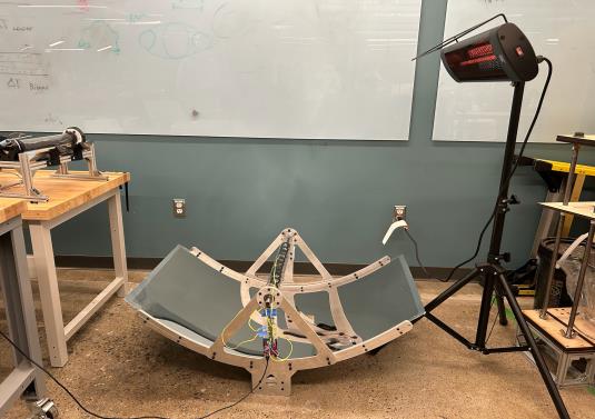
Trough Indoor Testing
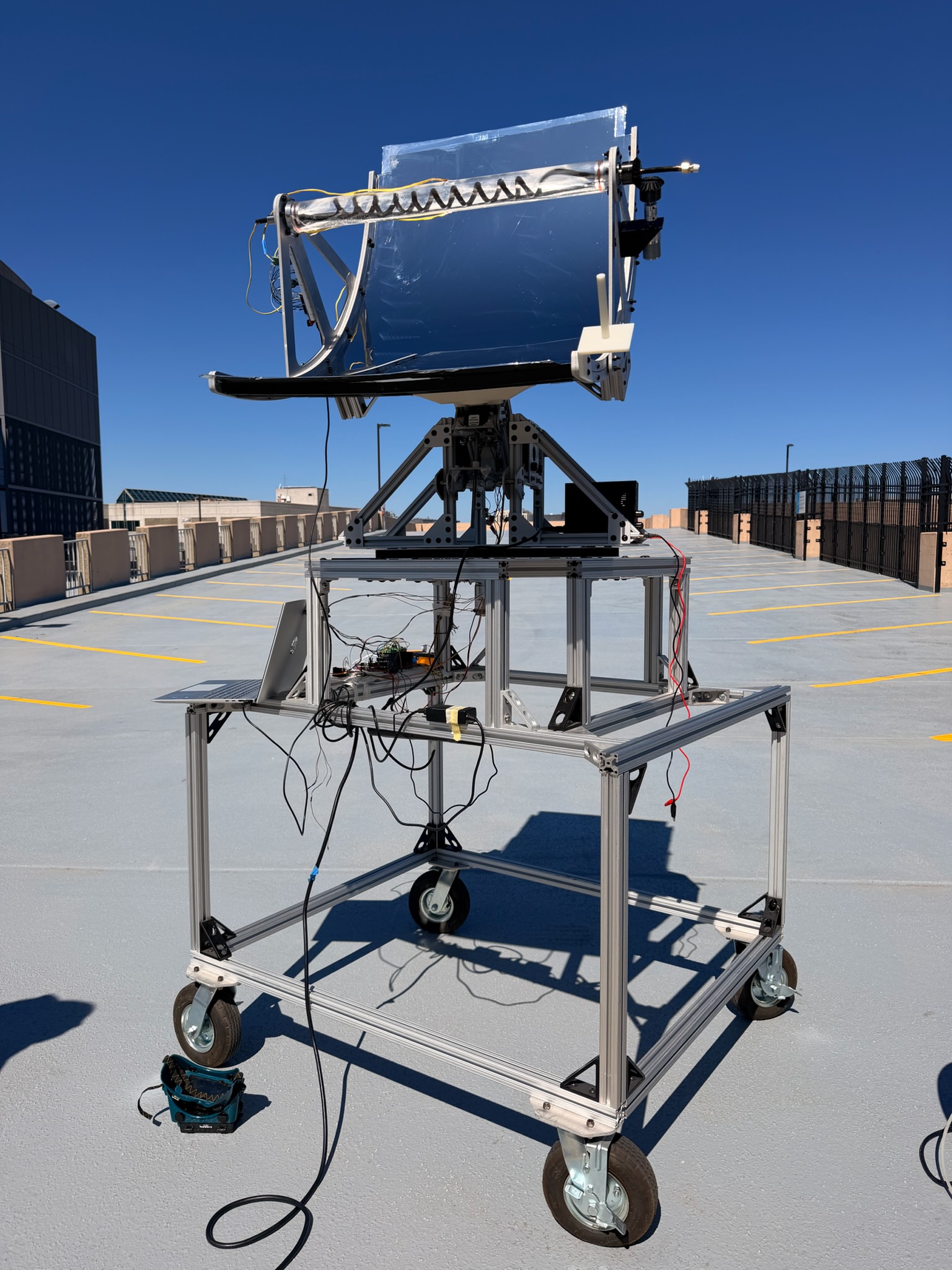
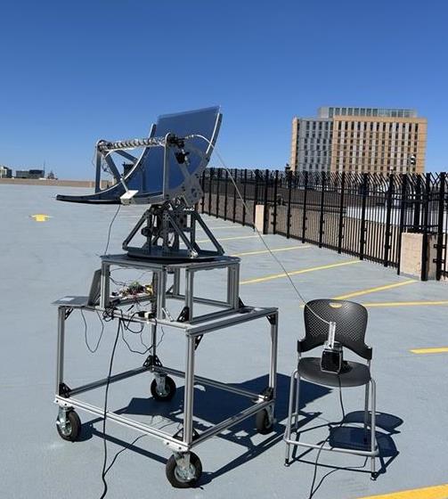
Trough Outdoor Testing
Key Design Decisions
Coil Geometry
| Geometry | Length (in) | Air residence (s) | Surface area (in²) |
|---|---|---|---|
| Straight | 22 | 0.2 | 26 |
| Coil | 62 | 0.5 | 73 |
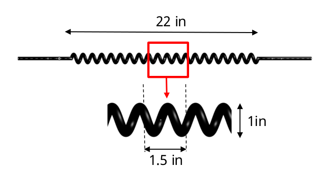
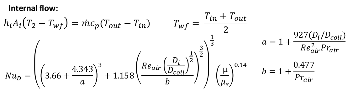
~3× increase in air residence time and surface area with the coil geometry. Performed fluids and heat transfer analysis using MATLAB and hand calculations to validate a coiled copper tube geometry, applying a Nusselt number correlation for coiled-tube internal flow that accounts for the tube-to-coil diameter ratio alongside the Reynolds and Prandtl numbers of the internal airflow:
Rotational Cap
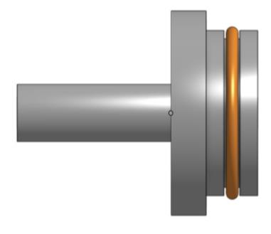
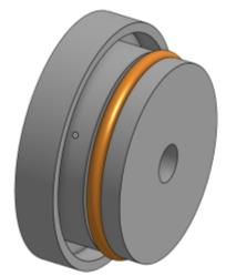
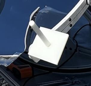
- High-temp O-ring for seal strength
- High-temp silicone sealant
- Single bearing for axial rotation
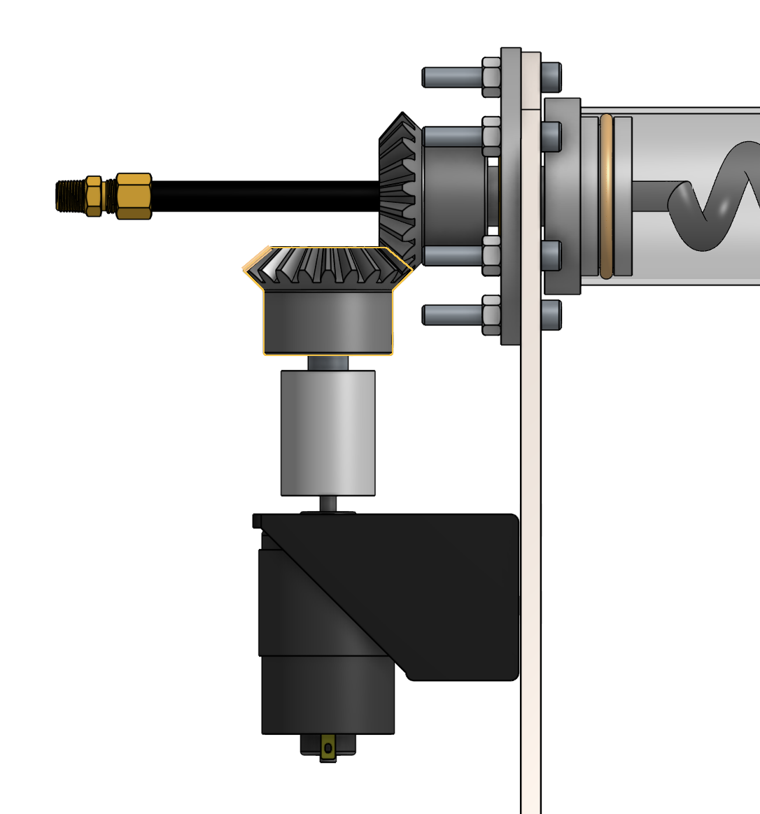
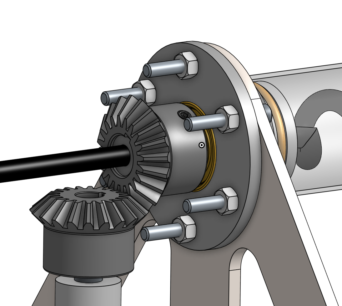
Motor & Rotation
- Bevel gears drive the rotational subassembly
- DC motor with dedicated motor mount
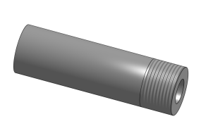
- Coupler links motor to the end flange (bearing press fit)
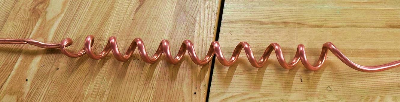
Copper Tube Fabrication
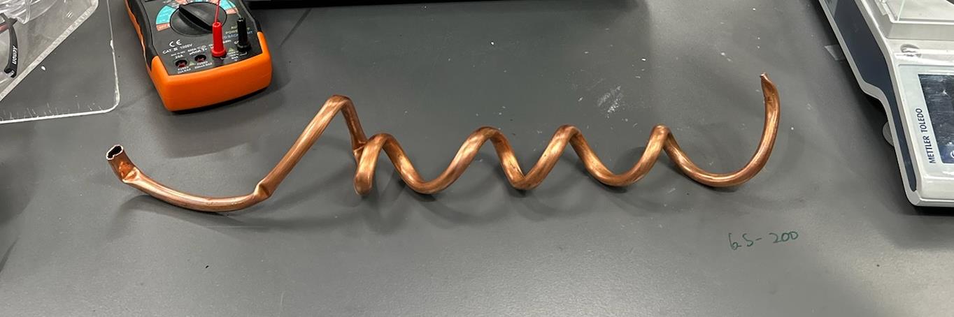
The capstone machine shop couldn't fabricate the helical coil, and an external vendor quoted ~$700–800 for a single unit. We worked with the machinist and online resources to develop an in-house method through trial and error.

Particle Selection
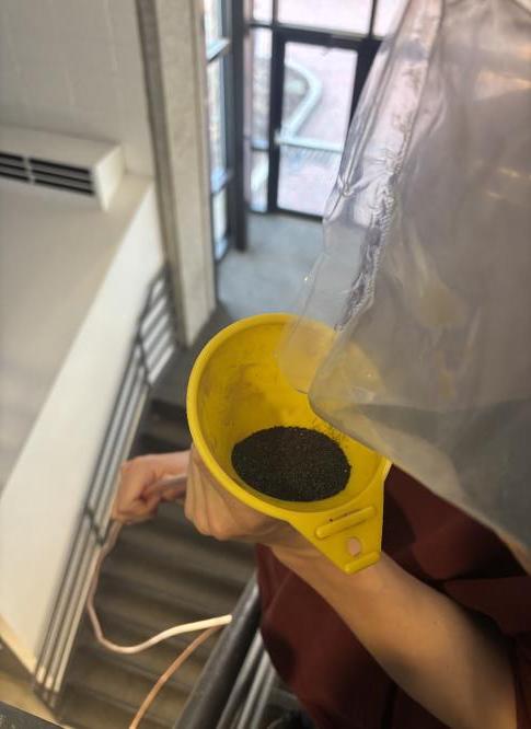
Two rounds of heat-lamp testing narrowed candidate particles down by absorptivity, weight, thermal conductivity, and cooling rate.
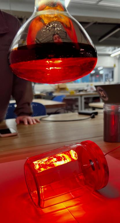
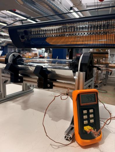
Silicon carbide was selected for its lower cooling rate and lack of glass-tube shading. The 200g test quantity was scaled proportionally to the full 22″ focal tube, landing at 340g.

Final Testing
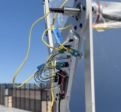
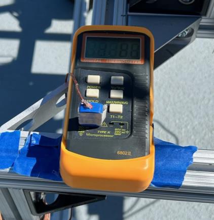
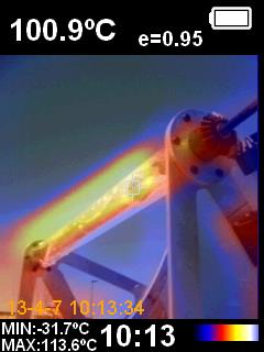
We reserved the Columbus Garage rooftop and waited for a sunny day, then tested with and without particles at three flow rates: 5, 10, and 20 L/min.
| Metric | With Particles | Without Particles |
|---|---|---|
| Average ambient temp | 8°C | 19°C |
| Max outlet temp | 161°C | 174°C |
| Max glass tube temp | 173°C | 144°C |
Final Conclusions
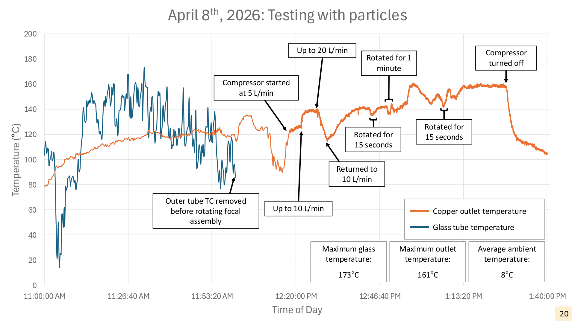
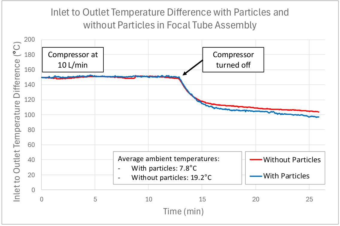
- No significant difference found in outlet temperature with particles in the system
- Particles elevate glass tube assembly temperature
- Enhanced heat retention found with particles in indoor testing
- System rotation resulted in small temperature bumps
Future Improvements
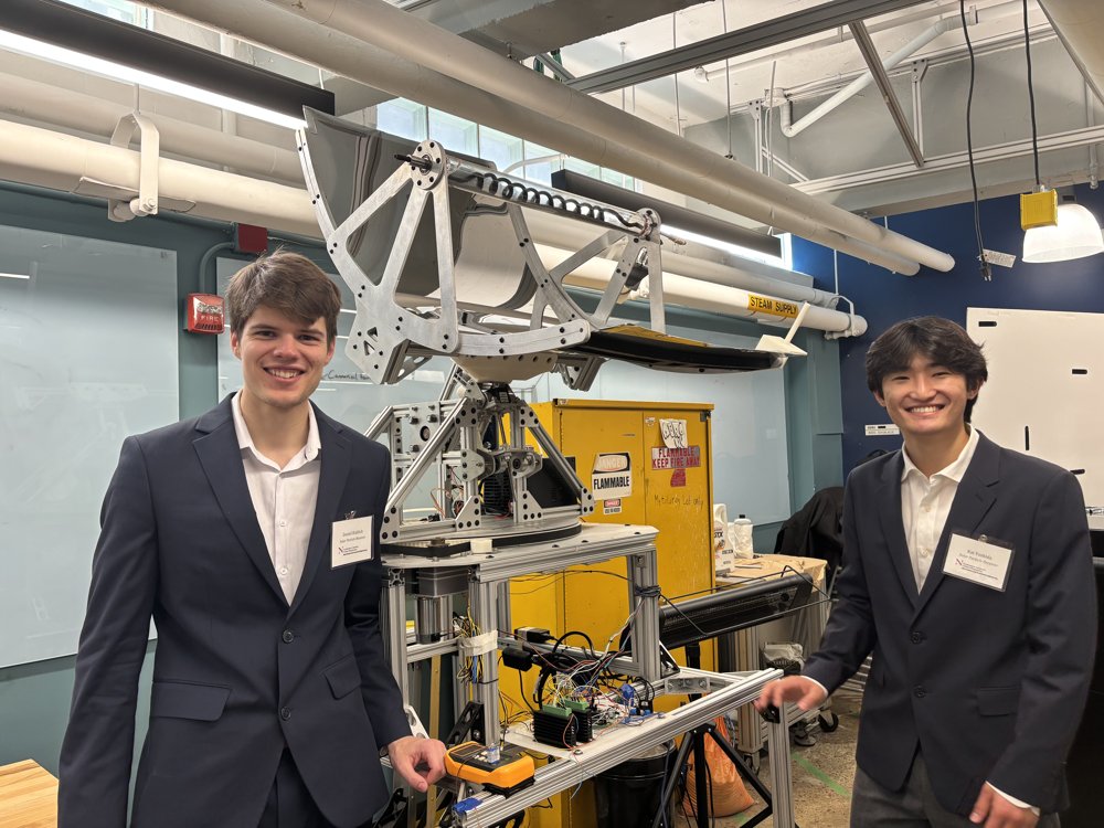
- Improved assembly process
- Copper tubing fabrication
- Testing across varied weather conditions
- Particle fluidization
- Energy storage